Security Systems  Central Vacuums  Satellite & Antennas  About Us  Contact Us  Links Audio/Video  Carpet Spot Removers  HOME  (719) 495-2715
Diagrams Back to Security Systems Pictures 1 Pictures 2
Black Forest Home Security Systems, the only company that gives you everyting you pay for: quality, craftsmanship and personal service. We know how to do it right and we care about doing it right!
Click For Music

As an instructor for the National Training School division of the National Burglar and Fire Alarm Association (now called the Electronic Security Associatin), Dave tries to impress upon student installers the vital importance of properly installing security systems.

One of the many common problems Dave sees in the field is incorrectly wired detection circuits. These educational diagrams show consumers how security system circuits should be wired. Most of the security systems Dave looks at are installed incorrectly. Consumers should understand that not everyone who claims to be a security "professional" does their work to professional standards. Consumers must choose their security provider very carefully because the wrong decision could literally cost them their lives.

National Burglar and Fire Alarm Association instructor Dave Easely at the board teaching students about proper wiring methods for detection circuits
All of the instructors for the National Burglar and Fire Alarm Association are committed to sharing their knowledge with others in the hope it will raise the quality of installations, increase consumer confidence in nationally certified technicians and raise the professionalism of our industry.

   Continued Below  

Basic security system detection circuit showing one wire leaving the control panel going out to an end of line resistor correctly installed at the detection device. A second wire then leaves the detection device and returns to the control panel. Because the detection device is secure, normal electrical current flows in the circuit.

Black Forest Home Security Systems

In figure 1 Dave has drawn a typical security system circuit. A pair of wires runs from the control panel through the attic, crawl space, or walls to the detection device, which could be a door or window contact or a motion detector. The alarm circuit works much like an electric light circuit in your home. When you close the switch electric current will flow through the circuit, illuminating the light bulb. Open the switch and the electric current flow stops.

The end of line resistor is correctly placed at the farthest point away from the control panel, at the detection device. The resistor "resists" or limits current flow in the circuit to a precise small amount, just as the nozzle on a garden hose can resist or limit the flow of water to just a trickle. The control panel constantly monitors the flow of electric current through the circuit, looking for the precise amount.

   Continued Below  

In This circuit the detection device has been triggered, opening the circuit. Electrical current flow stops causing an alarm.

Black  Forest Home Security Systems

Figure 3 shows a break in the wire between the control panel and the end of line resistor at the detection device. The break stops current flow and causes an alarm even though the detection device is secure.

The control panel will go into alarm if the electric current flow increases or decreases from the precise amount. This is called a supervised circuit because the control panel knows what the precise electric current flow should be and any variation from normal, increase or decrease, causes an alarm.

In figure 2 Dave Easley shows the circuit in a violated state. The detection device has been triggered, causing it to open the circuit. Normal current flow stops and the control panel shows alarm.

In figure 3 Dave shows the circuit with a wire cut between the control panel and the detection device. The wire could be cut either accidently or intentionally by someone doing work in the building. Normal current flow stops and the control panel shows alarm.

   Continued Below  

Figure 4 shows a short accross the wires between the control panel and the end of line resistor at the detection device. The short effectively removes the end of line resistor and the detection device from the circuit. Removing the current limiting effect of the end of line resistor causes higher current flow and an alarm, even though the detection device is secure.

Black Forest Home Security Systems

In figure 4 Dave Easley shows the circuit with a short between the control panel and the detection device. The wires could be shorted either accidentally or intentionally by someone doing work in the building. Current flows through the short instead of the detection device. The short effectively removes the detection device from the security system. The short also removes the end of line resistor from the circuit. Even though the detection device is secure, there is no longer the precise resistance limiting the current flow, the current flow increases and the control panel shows alarm. Because of the correctly placed end of line resistor, the control panel is able to detect a short and notify the security system user of the problem with the circuit. Most of the security systems Dave sees in Colorado Springs are wired incorrectly, not like this diagram.

   Continued Below  

Figure 5 shows an incorrectly wired circuit with the end of line resistor inside the control panel. In spite of the fact that the end of line resistor is in the wrong place the circuit works correctly. The resistor limits current flow, the detection device is secure and everything works properly

Figure 6 shows the incorrectly wired circuit with the detection device triggered. This opens the circuit, current flow stops and causes an alarm. Again everything works OK

Black Forest Home Security Systems

Figures 5 through 9 show circuits installed by an ignorant or apathetic installer. The end of line resistor is incorrectly placed at the control panel. Let's see what happens!

In figure 5 Dave shows the detection device secure. The end of line resistor limits the current flow to the precise amount and everything is operating properly in spite of the fact that the end of line resistor is in the wrong place.

In figure 6 Dave shows the detection device violated, opening the circuit. Normal current flow stops and the control panel shows alarm. Still operating properly. Even though the end of line resistor is incorrectly placed inside the control panel.

   Continued Below  

Figure 7 shows the incorrectly wired circuit with a break in the wire between the end of line resistor inside the control panel and the detection device. The break stops current flow and causes an alarm even though the detection device is secure. Again, the circuit works properly in spite of the fact it is wired incorrectly.

Figure 8 shows a short in the wires between the end of line resistor incorrectly placed inside the control panel and the detection device. The short effectively removes the detection device from the circuit but because the end of line resistor is inside the control panel it still limits the current flow to the correct amount. The panel doesn't know the circuit has been defeated!

Black Forest Home Security Systems

In figure 7 Dave Easley shows a wire cut. Even though the detection device is secure, the circuit is broken and current flow stops. The control panel will show alarm. Still operating as it should in spite of the misplaced end of line resistor.

In figure 8 Dave shows a short in the wire between the control panel and the end of line resistor. However, because the end of line resistor is incorrectly placed inside the control panel, it still limits the current flow to the precise amount so the control panel shows everything secure. Electrical current flows through the short instead of the detection device. The detection device is effectively removed from the security system but the control panel doesn't know it! Neither will the system owner.

   Continued Below  

Figure 9 shows the result of the combination of a resistor incorrectly placed inside the control panel and a short. The detection device is triggered but their is NO alarm!

Figure 4 shows a short accross the wires between the control panel and the end of line resistor at the detection device. The short effectively removes the end of line resistor and the detection device from the circuit. Removing the current limiting effect of the end of line resistor causes higher current flow and an alarm, even though the detection device is secure.

Black Forest Home Security Systems

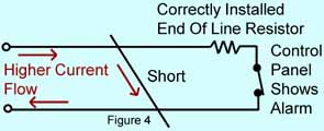
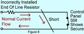
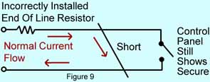
In figure 9 Dave shows what can happen. The detection device is triggered but there is NO ALARM because the end of line resistor is in the wrong place! Compare figures 8 and 9 with the correctly installed figure 4, shown again for comparison.

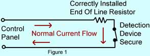
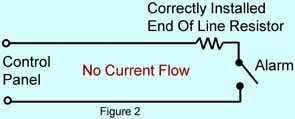
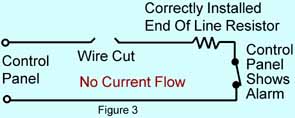
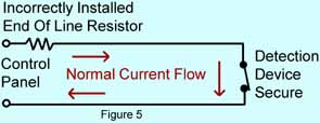
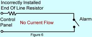
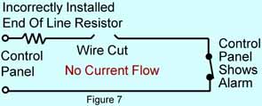
When the end of line resistor is incorrectly installed in the control panel, the security system will work correctly MOST of the time but not ALL of the time. A short in the wires can cause the system to work improperly. The correct placement of the end of line resistor is critical for proper supervision of the circuit.

Now that you know what to look for, go to Pictures 1 to see just a few of the many improperly installed security systems in the Colorado Springs, Colorado area.

Let Dave do it right the first time!

   Continued Below  

If you are an installer and would like to receive training to become a nationally certified alarm technician, contact the Colorado Burglar and Fire Alarm Association at (303) 805-0885 and ask about the next class. Currently there are three classes, one basic and two advanced.

If you are a burglar, keep in mind that the prisons and the grave yards are filled with burglars who thought they could get around alarm systems. The lucky ones were caught by the police. The unlucky ones were caught by a homeowner who was armed. Colorado has a make my day law. Homeowners who are in fear of bodily harm from a burglar in their home may kill the burglar and cannot be tried criminally or sued civilly.

   BACK TO TOP